Four-Cylinder
Car Engines.
|
|
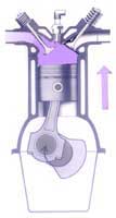
Principle:
The four cylinder internal combustion engine,
during the four stroke cycle, converts the chemical energy
stored in their fuels into heat energy when fuel is burnt.
The fuel energy is converted into mechanical energy by the
expansion of gases against pistons. The pistons as a result
undergo a forward and backward motion. This forward
and backward motion moves a connecting
rod which in turn makes the crankshaft rotate. It is this
rotatory motion which passes through gears and finally makes
the wheels rotate.
The four stroke cycle |
|
|
|
|
|
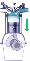
Induction
stroke:
The inlet valve is open, the exhaust valve closed. The piston
descends, inducing a flow of mixture. Soon after this stroke,
the inlet valve is closed. |
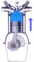
Compression
stroke :
Both inlet and exhaust valves are closed. The rising piston
compresses the mixture in the combustion chamber and compression
heat vaporises the mixture. |
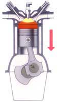
Power
stroke:
Both valves remain closed. The compressed gas is ignited by
a spark from the spark-plug. Expansion of burning gas drives
the piston down. Exhaust valve opens. |
Exhaust
stroke:
The inlet valve is closed, and exhaust valve open. The piston
rises to expel burnt gases, inlet valve opens, exhaust valve
closes. Then the cycle restarts. |
| |
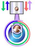 |
Arrows
indicate strokes of piston and related coloured lines show
period valves are open. |
|
|
Pressure
on the piston causes it and the connecting rod to move downwards,
and rotate the crankshaft. Four cranks together complete the crankshaft;
each crank has a piston and connecting rod to turn it.
| Arrangement
of the Cranks |
A - Front end
for fitting pully or vibration damper
B - Web extension serves as balance weight
C - Journal of crankshaft rotates in a main bearing
D - Crankpin carries big-end of connecting rod linked
to piston
E - Flange to which flywheel is bolted
|
 Fig (A)
|
With a four-cylinder
engine, a 180-degree crank-shaft, arranged as shown in Fig(A)
always is used. The crank arms for No.1 and 4 cylinders project
in the same direction, and the crank arms for No.2 and 3 cylinders
project from the opposite side of the crankshaft. In the four-cylinder
engine, No. 1 and 4 piston are always moving in the opposite
direction from pistons No.2 and 3 . This arrangement tends
to neutralize the primary inertia forces as, if the pistons
are equal in weight, they will balance each other and give
good primary mechanical balance. (Hence the angle between
the pairs of throws is 180 degrees.) |
| Firing
Order |
|
| Table
1 (American Standard) |
| Cylinder |
1 |
2 |
3 |
4 |
| 1st
revolution |
P |
E |
C |
I |
| E |
I |
P |
C |
| 2nd
revolution |
I |
C |
E |
P |
| C |
P |
I |
E |
| |
| Table
2 (Regular - The moving image above) |
| Cylinder |
1 |
2 |
3 |
4 |
| 1st
revolution |
P |
C |
E |
I |
| E |
P |
I |
C |
| 2nd
revolution |
I |
E |
C |
P |
| C |
I |
P |
E |
|
Also
the Fig.(A) will help to explain the firing order of a four
cylinder engine. Firing order is the sequence in which
the spark-plugs ignites a series of single sparks per cylinder,
in the cylinders. As No 1 piston moves downward on power,
No 4 piston must move downward on induction; No 2 piston can
be moving upward on exhaust or compression and No 3 piston
will be moving upward on compression or exhaust. Table
1 shows the power balance with No 2 piston on exhaust
and No 3 piston on compression. Table 2 shows the power
balance rusulting from No 2 piston moving upward on compression
and No 3 on exhaust. With either arrangement the power impulses
are evenly distributed, that is, they are 180 degrees apart.
Each arrangement gives a different firing order. That of table
1 gives a firing order of 1-3-4-2 and that of table 2, a firing
order of 1-2-4-3. American four-cylinder passenger cars have
standardized on a firing order of 1-3-4-2. If the firing order
were to be 1-2-3-4, the crankshaft and engine mountings would
be subjected to considerable stress and vibration.
|
| I
- Induction Stroke, C - Compression Stroke, P
- Power Stroke, E - Exhaust Stroke |
|